On the left, the Canopee transport carrier containing the European Service Module for NASA’s Artemis III mission arrives at Port Canaveral in Florida, on Tuesday, Sept. 3, 2024, before completing the last leg of its journey to the agency’s Kennedy Space Center’s Neil A. Armstrong Operations and Checkout via truck. On the right, NASA’s Pegasus barge, carrying several pieces of hardware for Artemis II, III, and IV arrives at NASA Kennedy’s Launch Complex 39 turn basin wharf on Thursday, Sept. 5, 2024. Credit: NASA
From across the Atlantic Ocean and through the Gulf of Mexico, two ships converged, delivering key spacecraft and rocket components of NASA’s Artemis campaign to the agency’s Kennedy Space Center in Florida.
On Sept. 3, ESA (European Space Agency) marked a milestone in the Artemis III mission as its European-built service module for NASA’s Orion spacecraft completed a transatlantic journey from Bremen, Germany, to Port Canaveral, Florida, where technicians moved it to nearby NASA Kennedy. Transported aboard the Canopée cargo ship, the European Service Module—assembled by Airbus with components from 10 European countries and the U.S.—provides propulsion, thermal control, electrical power, and water and oxygen for its crews.
“Seeing multi-mission hardware arrive at the same time demonstrates the progress we are making on our Artemis missions,” said Amit Kshatriya, deputy associate administrator, Moon to Mars Program, at NASA Headquarters in Washington. “We are going to the Moon together with our industry and international partners and we are manufacturing, assembling, building, and integrating elements for Artemis flights.”
NASA’s Pegasus barge, the agency’s waterway workhorse for transporting large hardware by sea, ferried multi-mission hardware for the agency’s SLS (Space Launch System) rocket, the Artemis II launch vehicle stage adapter, the “boat-tail” of the core stage for Artemis III, the core stage engine section for Artemis IV, along with ground support equipment needed to move and assemble the large components. The barge pulled into NASA Kennedy’s Launch Complex 39B Turn Basin Thursday.
The spacecraft factory inside NASA Kennedy’s Neil Armstrong Operations and Checkout Building is set to buzz with additional activity in the coming months. With the Artemis II Orion crew and service modules stacked together and undergoing testing, and engineers outfitting the Artemis III and IV crew modules, engineers soon will connect the newly arrived European Service Module to the crew module adapter, which houses electronic equipment for communications, power, and control, and includes an umbilical connector that bridges the electrical, data, and fluid systems between the crew and service modules.
The SLS rocket’s cone-shaped launch vehicle stage adapter connects the core stage to the upper stage and protects the rocket’s flight computers, avionics, and electrical devices in the upper stage system during launch and ascent. The adapter will be taken to Kennedy’s Vehicle Assembly Building in preparation for Artemis II rocket stacking operations.
The boat-tail, which will be used during the assembly of the SLS core stage for Artemis III, is a fairing-like structure that protects the bottom end of the core stage and RS-25 engines. This hardware, picked up at NASA’s Michoud Assembly Facility in New Orleans, will join the Artemis III core stage engine section housed in the spaceport’s Space Systems Processing Facility.
The Artemis IV SLS core stage engine section arrived from NASA Michoud and also will transfer to the center’s processing facility ahead of final assembly.
Under the Artemis campaign, NASA will land the first woman, first person of color, and its first international partner astronaut on the lunar surface, establishing long-term exploration for scientific discovery and preparing for human missions to Mars. The agency’s SLS rocket and Orion spacecraft, and supporting ground systems, along with the human landing system, next-generation spacesuits and rovers, and Gateway, serve as NASA’s foundation for deep space exploration.
For more information on NASA’s Artemis missions, visit:
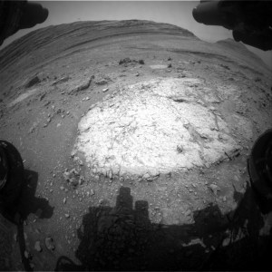
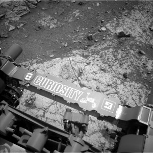
This image was taken by Left Navigation Camera aboard NASA’s Mars rover Curiosity on sol 4289 — Martian day 4,289 of the Mars Science Laboratory mission — on Aug. 30, 2024 at 03:48:38 UTC. To the left of the crescent-shaped formation in the low-center part of the image, a wheel track is visible along with an “intriguing” batch of shattered rock where Curiosity had previously driven.
NASA/JPL-Caltech
Earth planning date: Friday, Aug. 30, 2024
Our backwards drive to “McDonald Pass” got hung up on the steep slopes of “Fairview Dome,” but unlike a lot of movie sequels, our inadvertent return visit to Fairview Dome was at least as good as the original. We took full advantage of the chance to investigate this bedrock rise within Gediz Vallis with multiple contact and remote science targets.
MAHLI and APXS paired up on two different DRT targets of more- and less-nodular spots of bedrock at “Lower Boy Scout Lake” and “Upper Boy Scout Lake.” You can see in the Navcam image above that just beyond the bedrock slab we stopped on, there is a wheel track and a shattered batch of rock. We crushed that bit of rock as we drove backward and were left with a great view of it, including some intriguing bright rock interiors. ChemCam targeted one of those bright rock faces at “North Palisade” and Mastcam acquired a mosaic across the whole field of broken rocks at “Ritter-Banner Saddle.” The churned-up sand of Ritter-Banner Saddle also made for a convenient change detection target as we keep our eye on the wind effects of a potential dust storm rising on Mars. ChemCam had two other opportunities for LIBS analyses at a nodular bedrock target called “Regulation Peak,” and another intriguing vertical rock face with strong color differences called “Simmons Peak.” ChemCam used RMI mosaics to image a collection of higher albedo rocks in Gediz Vallis at a site called “Buckeye Ridge.” Mastcam planned a mosaic of a different part of Gediz Vallis that is in the direction we are driving next, which will help plot those drives and also give us some insight into the boulders strewn about that part of the valley. Closer to the rover, the “Outguard Spire” target was of interest for Mastcam imaging because of its color zonation — the way colors are distributed across different areas, or zones, of the rock. It’s the kind of zonation we intend to study at McDonald Pass. The trough of sand at the “Whitney-Russell Pass” target was of interest for its potential insights into how bedrock blocks break up on Mars.
Monitoring the potential rise of a dust storm meant that the plan was busy with environmental observations. ChemCam acquired a passive sky observation, Navcam collected two rounds of dust-devil imaging, cloud movies, and atmospheric dust measurements, Mastcam acquired multiple atmospheric dust measurements, and REMS ran in longer blocks throughout each sol than it does in normal weather conditions. Dust or not, RAD and DAN passive were planned regularly through the three sols of the plan.
Written by Michelle Minitti, Planetary Geologist at Framework
Rocket Hardware for Future Artemis Flights Moved to Barge for Delivery to Kennedy
NASA is making strides with the Artemis campaign as key components for the SLS (Space Launch System) rocket continue to make their way to NASA’s Kennedy Space Center. Teams with NASA and Boeing loaded the core stage boat-tail for Artemis III and the core stage engine section for Artemis IV onto the agency’s Pegasus barge at Michoud Assembly Facility on Aug. 28.
The core stage engine section of the SLS (Space Launch System) rocket for Artemis IV is loaded onto the agency’s Pegasus barge at Michoud Assembly Facility on Aug. 28. The core stage hardware will be moved Kennedy’s Space Systems Processing Facility for outfitting.
NASA/Justin Robert
The core stage hardware joins the launch vehicle stage adapter for Artemis II, which was moved onto the barge at NASA’s Marshall Space Flight Center on Aug. 21. Pegasus will ferry the multi-mission rocket hardware more than 900 miles to the Space Coast of Florida. Teams with the NASA’s Exploration Ground Systems Program will prepare the launch vehicle stage adapter for Artemis II stacking operations inside the Vehicle Assembly Building, while the core stage hardware will be moved to Kennedy’s Space Systems Processing Facility for outfitting. Beginning with Artemis III, core stages will undergo final assembly at Kennedy.
The launch vehicle stage adapter is essential for connecting the rocket’s core stage to the upper stage. It also shields sensitive avionics and electrical components in the rocket’s interim cryogenic propulsion stage from the intense vibrations and noise of launch.
The boat-tail and engine section are crucial for the rocket’s functionality. The boat-tail extends from the engine section, fitting snugly to protect the rocket’s engines during launch. The engine section itself houses more than 500 sensors, 18 miles of cables, and key systems for fuel management and engine control, all packed into the bottom of the towering 212-foot core stage.
NASA is working to land the first woman, first person of color, and its first international partner astronaut on the Moon under Artemis. SLS is part of NASA’s backbone for deep space exploration, along with the Orion spacecraft, supporting ground systems, advanced spacesuits and rovers, the Gateway in orbit around the Moon, and commercial human landing systems. SLS is the only rocket that can send Orion, astronauts, and supplies to the Moon in a single launch.
25 Years Strong: NASA’s Student Launch Competition Accepting 2025 Proposals
By Wayne Smith
NASA’s Student Launch competition kicks off its 25th year with the release of the 2025 handbook, detailing how teams can submit proposals by Sept. 11 for the event scheduled next spring near NASA’s Marshall Space Flight Center.
Student Launch is an annual competition challenging middle school, high school, and college students to design, build, test, and launch a high-powered amateur rocket with a scientific or engineering payload. After a team is selected, they must meet documentation milestones and undergo detailed reviews throughout the school year.
NASA’s Student Launch, a STEM competition, officially kicks off its 25th anniversary with the 2025 handbook.
NASA
Each year, NASA updates the university payload challenge to reflect current scientific and exploration missions. For the 2025 season, the payload challenge will again take inspiration from the Artemis missions, which seek to land the first woman and first person of color on the Moon.
As Student Launch celebrates its 25th anniversary, the payload challenge will include “reports” from STEMnauts, non-living objects representing astronauts. The 2024 challenge tasked teams with safely deploying a lander mid-air for a group of four STEMnauts using metrics to support a survivable landing. The lander had to be deployed without a parachute and had a minimum weight limit of five pounds.
“This year, we’re shifting the focus to communications for the payload challenge,” said John Eckhart, technical coordinator for Student Launch at Marshall. “The STEMnaut ‘crew’ must relay real-time data to the student team’s mission control. This helps connect Student Launch with the Artemis missions when NASA lands astronauts on the Moon.”
Thousands of students participated in the 2024 Student Launch competition – making up 70 teams representing 24 states and Puerto Rico. Teams launched their rockets to an altitude between 4,000 and 6,000 feet, while attempting to make a successful landing and executing the payload mission. The University of Notre Dame was the overall winner of the 2024 event, which culminated with a launch day open to the public.
Student Launch began in 2000 when former Marshall Director Art Stephenson started a student rocket competition at the center. It started with just two universities in Huntsville competing – Alabama A&M University and the University of Alabama in Huntsville – but has continued to soar. Since its inception, thousands of students have participated in the agency’s STEM competition, with many going on to a career with NASA.
“This remarkable journey, spanning a quarter of a century, has been a testament to the dedication, ingenuity, and passion of countless students, educators, and mentors who have contributed to the program’s success,” Eckhart said. “NASA Student Launch has been at the forefront of experiential education, providing students from middle school through university with unparalleled opportunities to engage in real-world engineering and scientific research. The program’s core mission – to inspire and cultivate the next generation of aerospace professionals and space explorers – has not only been met but exceeded in ways we could have only dreamed of.”
To encourage students to pursue degrees and careers in STEM (science, technology, engineering, and math), Marshall’s Office of STEM Engagement hosts Student Launch, providing them with real-world experiences. Student Launch is one of NASA’s nine Artemis Student Challenges – a variety of activities that expose students to the knowledge and technology required to achieve the goals of Artemis.
In addition to the NASA Office of STEM Engagement’s Next Generation STEM project, NASA Space Operations Mission Directorate, Northrup Grumman, National Space Club Huntsville, American Institute of Aeronautics and Astronautics, National Association of Rocketry, Relativity Space and Bastion Technologies provide funding and leadership for the competition.
“These bright students rise to a nine-month challenge for Student Launch that tests their skills in engineering, design, and teamwork,” said Kevin McGhaw, director of NASA’s Office of STEM Engagement Southeast Region. “They are the Artemis Generation, the future scientists, engineers, and innovators who will lead us into the future of space exploration.”
Smith, a Media Fusion employee and the Marshall Star editor, supports the Marshall Office of Communications.
NASA Expands Human Exploration Rover Challenge to Middle Schools
By Wayne Smith
Following a 2024 competition that garnered international attention, NASA is expanding its Human Exploration Rover Challenge (HERC) to include a remote control division and inviting middle school students to participate.
The 31st annual competition is scheduled for April 11-12, 2025, at the U.S. Space & Rocket Center, near NASA’s Marshall Space Flight Center. HERC is managed by NASA’s Southeast Regional Office of STEM Engagement at Marshall. The HERC 2025 Handbook has been released, with guidelines for the new remote control (RC) division – ROVR (Remote-Operated Vehicular Research) – and detailing updates for the human-powered division.
The cover of the HERC 2025 handbook, which is now available online.
NASA
“Our RC division significantly lowers the barrier to entry for schools who don’t have access to manufacturing facilities, have less funding, or who are motivated to compete but don’t have the technical mentorship required to design and manufacture a safe human-powered rover,” said Chris Joren, HERC technical coordinator. “We are also opening up HERC to middle school students for the first time. The RC division is inherently safer and less physically intensive, so we invite middle school teams and organizations to submit a proposal to be a part of HERC 2025.”
Another change for 2025 is the removal of task sites on the course for the human-powered rover division, allowing teams to focus on their rover’s design. Recognized as NASA’s leading international student challenge, the 2025 challenge aims to put competitors in the mindset of the Artemis campaign as they pitch an engineering design for a lunar terrain vehicle – they are astronauts piloting a vehicle, exploring the lunar surface while overcoming various obstacles.
“The HERC team wanted to put together a challenge that allows students to gain 21st century skills, workforce readiness skills, and skills that are transferable,” said Vemitra Alexander, HERC activity lead. “The students have opportunities to learn and apply the engineering design process model, gain public speaking skills, participate in community outreach, and learn the art of collaborating with their peers. I am very excited about HERC’s growth and the impact it has on the students we serve nationally and internationally.”
Students interested in designing, developing, building, and testing rovers for Moon and Mars exploration are invited to submit their proposals to NASA through Sept. 19.
More than 1,000 students with 72 teams from around the world participated in the 2024 challenge as HERC celebrated its 30th anniversary as a NASA competition. Participating teams represented 42 colleges and universities and 30 high schools from 24 states, the District of Columbia, Puerto Rico, and 13 other nations from around the world.
“We saw a massive jump in recognition, not only from within the agency as NASA Chief Technologist A.C. Charania attended the event, but with several of our international teams meeting dignitaries and ambassadors from their home countries to cheer them on,” Joren said. “The most impressive thing will always be the dedication and resilience of the students and their mentors. No matter what gets thrown at these students, they still roll up to the start line singing songs and waving flags.”
HERC is one of NASA’s eight Artemis Student Challenges reflecting the goals of the Artemis campaign, which seeks to land the first woman and first person of color on the Moon while establishing a long-term presence for science and exploration. NASA uses such challenges to encourage students to pursue degrees and careers in the STEM fields of science, technology, engineering, and mathematics.
Since its inception in 1994, more than 15,000 students have participated in HERC – with many former students now working at NASA, or within the aerospace industry.
Smith, a Media Fusion employee and the Marshall Star editor, supports the Marshall Office of Communications.
New NASA Sonifications Listen to the Universe’s Past
A quarter of a century ago, NASA released the “first light” images from the agency’s Chandra X-ray Observatory. This introduction to the world of Chandra’s high-resolution X-ray imaging capabilities included an unprecedented view of Cassiopeia A, the remains of an exploded star located about 11,000 light-years from Earth. Over the years, Chandra’s views of Cassiopeia A have become some of the telescope’s best-known images.
To mark the anniversary of this milestone, new sonifications of three images – including Cassiopeia A (Cas A) – are being released. Sonification is a process that translates astronomical data into sound, similar to how digital data are more routinely turned into images. This translation process preserves the science of the data from its original digital state but provides an alternative pathway to experiencing the data.
Sonifications of three images have been released to mark the 25th anniversary of Chandra’s “First Light” image. For Cassiopeia A, which was one of the first objects observed by Chandra, X-ray data from Chandra and infrared data from Webb have been translated into sounds, along with some Hubble data. The second image in the sonification trio, 30 Doradus, also contains Chandra and Webb data. NGC 6872 contains data from Chandra as well as an optical image from Hubble. Each of these datasets have been mapped to notes and sounds based on properties observed by these telescopes.
NASA/CXC/SAO/K.Arcand, SYSTEM Sounds (M. Russo, A. Santaguida)
This sonification of Cas A features data from Chandra as well as NASA’s James Webb, Hubble, and retired Spitzer space telescopes. The scan starts at the neutron star at the center of the remnant, marked by a triangle sound, and moves outward. Astronomers first saw this neutron star when Chandra’s inaugural observations were released 25 years ago this week. Chandra’s X-rays also reveal debris from the exploded star that is expanding outward into space. The brighter parts of the image are conveyed through louder volume and higher pitched sounds. X-ray data from Chandra are mapped to modified piano sounds, while infrared data from Webb and Spitzer, which detect warmed dust embedded in the hot gas, have been assigned to various string and brass instruments. Stars that Hubble detects are played with crotales, or small cymbals.
Another new sonification features the spectacular cosmic vista of 30 Doradus, one of the largest and brightest regions of star formation close to the Milky Way. This sonification again combines X-rays from Chandra with infrared data from Webb. As the scan moves from left to right across the image, the volume heard again corresponds to the brightness seen. Light toward the top of the image is mapped to higher pitched notes. X-rays from Chandra, which reveal gas that has been superheated by shock waves generated by the winds from massive stars, are heard as airy synthesizer sounds. Meanwhile, Webb’s infrared data show cooler gas that provides the raw ingredients for future stars. These data are mapped to a range of sounds including soft, low musical pitches (red regions), a wind-like sound (white regions), piano-like synthesizer notes indicating very bright stars, and a rain-stick sound for stars in a central cluster.
The final member of this new sonification triumvirate is NGC 6872, a large spiral galaxy that has two elongated arms stretching to the upper right and lower left, which is seen in an optical light view from Hubble. Just to the upper left of NGC 6872 appears another smaller spiral galaxy. These two galaxies, each of which likely has a supermassive black hole at the center, are being drawn toward one another. As the scan sweeps clockwise from 12 o’clock, the brightness controls the volume and light farther from the center of the image is mapped to higher-pitched notes. Chandra’s X-rays, represented in sound by a wind-like sound, show multimillion-degree gas that permeates the galaxies. Compact X-ray sources from background galaxies create bird-like chirps. In the Hubble data, the core of NGC 6872 is heard as a dark low drone, and the blue spiral arms (indicating active star formation) are audible as brighter, more highly pitched tones. The background galaxies are played as a soft pluck sound while the bright foreground star is accompanied by a crash cymbal.
More information about the NASA sonification project through Chandra, which is made in partnership with NASA’s Universe of Learning, can be found here. The collaboration was driven by visualization scientist Kimberly Arcand (CXC), astrophysicist Matt Russo, and musician Andrew Santaguida, (both of the SYSTEM Sounds project), along with consultant Christine Malec.
NASA’s Universe of Learning materials are based upon work supported by NASA under cooperative agreement award number NNX16AC65A to the Space Telescope Science Institute, working in partnership with Caltech/IPAC, Center for Astrophysics | Harvard & Smithsonian, and the Jet Propulsion Laboratory.
Chandra, managed for NASA by the agency’s Marshall Space Flight Center in partnership with the CXC, is one of NASA’s Great Observatories, along with the Hubble Space Telescope and the now-retired Spitzer Space Telescope and Compton Gamma Ray Observatory. It was first proposed to NASA in 1976 by Riccardo Giacconi, recipient of the 2002 Nobel Prize for Physics based on his contributions to X-ray astronomy, and Harvey Tananbaum, who would later become the first director of the Chandra X-ray Center. Chandra was named in honor of the late Nobel laureate Subrahmanyan Chandrasekhar, who earned the Nobel Prize in Physics in 1983 for his work explaining the structure and evolution of stars.
Europa Clipper Gets Set of Super-Size Solar Arrays
NASA’s Europa Clipper spacecraft recently got outfitted with a set of enormous solar arrays at the agency’s Kennedy Space Center. Each measuring about 46½ feet long and about 13½ feet high, the arrays are the biggest NASA has ever developed for a planetary mission. They must be large so they can soak up as much sunlight as possible during the spacecraft’s investigation of Jupiter’s moon Europa, which is five times farther from the Sun than Earth is.
NASA’s Europa Clipper is seen Aug. 21 at the agency’s Kennedy Space Center. Engineers and technicians deployed and tested the giant solar arrays to be sure they will operate in flight.
NASA/Frank Michaux
The arrays have been folded up and secured against the spacecraft’s main body for launch, but when they’re deployed in space, Europa Clipper will span more than 100 feet – a few feet longer than a professional basketball court. The “wings,” as the engineers call them, are so big that they could only be opened one at a time in the clean room of Kennedy’s Payload Hazardous Servicing Facility, where teams are readying the spacecraft for its launch period, which opens Oct. 10.
Meanwhile, engineers continue to assess tests conducted on the radiation hardiness of transistors on the spacecraft. Longevity is key, because the spacecraft will journey more than five years to arrive at the Jupiter system in 2030. As it orbits the gas giant, the probe will fly by Europa multiple times, using a suite of science instruments to find out whether the ocean underneath its ice shell has conditions that could support life.
Powering those flybys in a region of the solar system that receives only 3% to 4% of the sunlight Earth gets, each solar array is composed of five panels. Designed and built at the Johns Hopkins Applied Physics Laboratory (APL) in Laurel, Maryland, and Airbus in Leiden, Netherlands, they are much more sensitive than the type of solar arrays used on homes, and the highly efficient spacecraft will make the most of the power they generate.
NASA’s Europa Clipper is seen in a clean room at Kennedy Space Center after engineers and technicians tested and stowed the spacecraft’s giant solar arrays.
NASA/Frank Michaux
At Jupiter, Europa Clipper’s arrays will together provide roughly 700 watts of electricity, about what a small microwave oven or a coffee maker needs to operate. On the spacecraft, batteries will store the power to run all of the electronics, a full payload of science instruments, communications equipment, the computer, and an entire propulsion system that includes 24 engines.
While doing all of that, the arrays must operate in extreme cold. The hardware’s temperature will plunge to minus 400 degrees Fahrenheit when in Jupiter’s shadow. To ensure that the panels can operate in those extremes, engineers tested them in a specialized cryogenic chamber at Liège Space Center in Belgium.
“The spacecraft is cozy. It has heaters and an active thermal loop, which keep it in a much more normal temperature range,” said APL’s Taejoo Lee, the solar array product delivery manager. “But the solar arrays are exposed to the vacuum of space without any heaters. They’re completely passive, so whatever the environment is, those are the temperatures they get.”
About 90 minutes after launch, the arrays will unfurl from their folded position over the course of about 40 minutes. About two weeks later, six antennas affixed to the arrays will also deploy to their full size. The antennas belong to the radar instrument, which will search for water within and beneath the moon’s thick ice shell, and they are enormous, unfolding to a length of 57.7 feet, perpendicular to the arrays.
“At the beginning of the project, we really thought it would be nearly impossible to develop a solar array strong enough to hold these gigantic antennas,” Lee said. “It was difficult, but the team brought a lot of creativity to the challenge, and we figured it out.”
Europa Clipper’s three main science objectives are to determine the thickness of the moon’s icy shell and its interactions with the ocean below, to investigate its composition, and to characterize its geology. The mission’s detailed exploration of Europa will help scientists better understand the astrobiological potential for habitable worlds beyond our planet.
Managed by Caltech in Pasadena, California, NASA’s Jet Propulsion Laboratory leads the development of the Europa Clipper mission in partnership with APL for NASA’s Science Mission Directorate. APL designed the main spacecraft body in collaboration with JPL and NASA’s Goddard Space Flight Center. The Planetary Missions Program Office at NASA’s Marshall Space Flight Center executes program management of the Europa Clipper mission.
NASA’s Launch Services Program, based at Kennedy, manages the launch service for the Europa Clipper spacecraft, which will launch on a SpaceX Falcon Heavy rocket from Launch Complex 39A at Kennedy.
Work is Underway on NASA’s Next-Generation Asteroid Hunter
NASA’s new asteroid-hunting spacecraft is taking shape at NASA’s Jet Propulsion Laboratory. Called NEO Surveyor (Near-Earth Object Surveyor), this cutting-edge infrared space telescope will seek out the hardest-to-find asteroids and comets that might pose a hazard to our planet. In fact, it is the agency’s first space telescope designed specifically for planetary defense.
Targeting launch in late 2027, the spacecraft will travel a million miles to a region of gravitational stability – called the L1 Lagrange point – between Earth and the Sun. From there, its large sunshade will block the glare and heat of sunlight, allowing the mission to discover and track near-Earth objects as they approach Earth from the direction of the Sun, which is difficult for other observatories to do. The space telescope also may reveal asteroids called Earth Trojans, which lead and trail our planet’s orbit and are difficult to see from the ground or from Earth orbit.
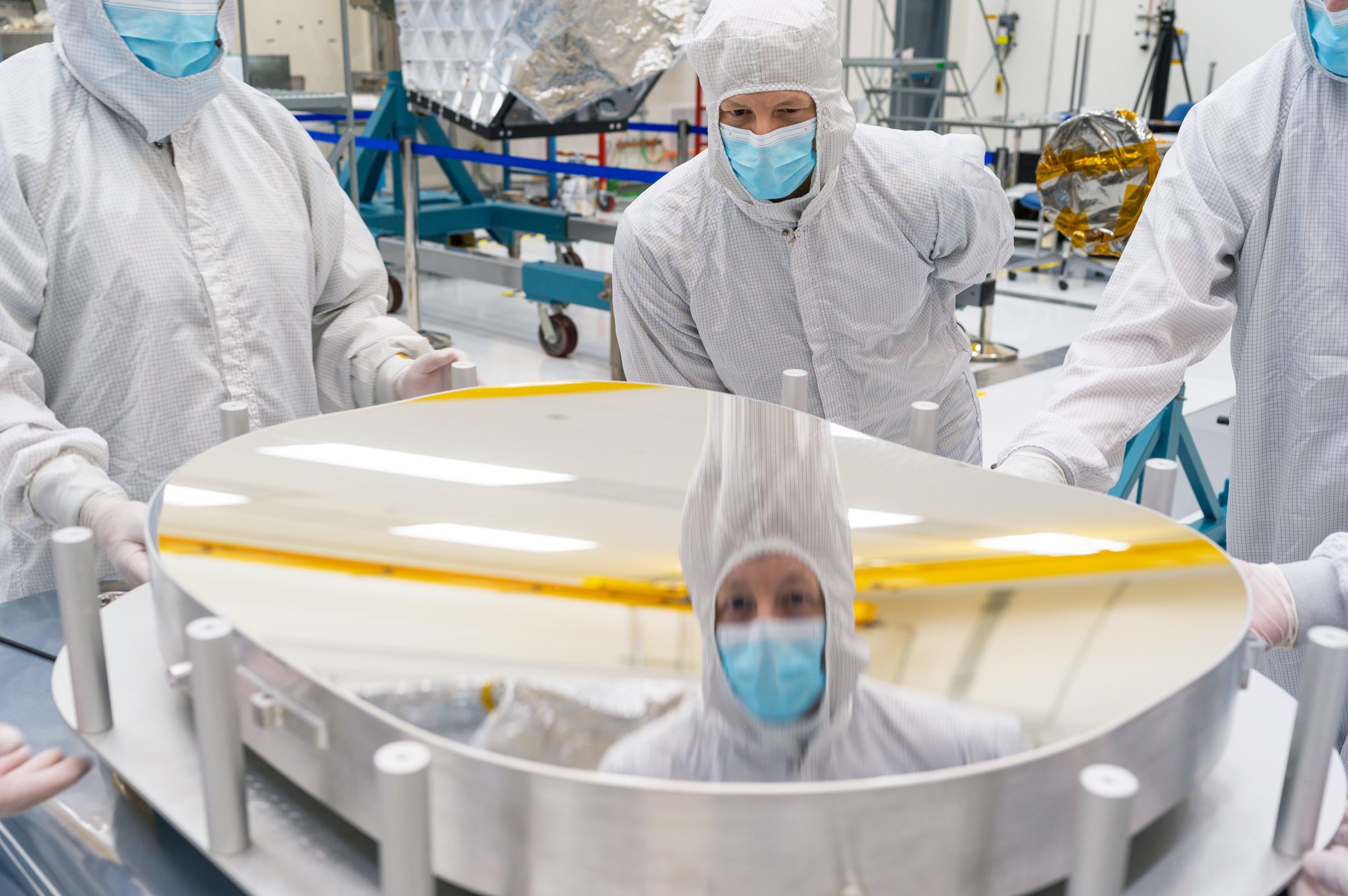
A mirror that was later installed inside NASA’s Near-Earth Object Surveyor shows a reflection of principal optical engineer Brian Monacelli during an inspection of the mirror’s surface at the agency’s Jet Propulsion Laboratory on July 17.
NASA/JPL-Caltech
NEO Surveyor relies on cutting-edge detectors that observe two bands of infrared light, which is invisible to the human eye. Near-Earth objects, no matter how dark, glow brightly in infrared as the Sun heats them. Because of this, the telescope will be able to find dark asteroids and comets, which don’t reflect much visible light. It also will measure those objects, a challenging task for visible-light telescopes that have a hard time distinguishing between small, highly reflective objects and large, dark ones.
“NEO Surveyor is optimized to help us to do one specific thing: enable humanity to find the most hazardous asteroids and comets far enough in advance so we can do something about them,” said Amy Mainzer, survey director for NEO Surveyor and a professor at the University of California, Los Angeles. “We aim to build a spacecraft that can find, track, and characterize the objects with the greatest chance of hitting Earth. In the process, we will learn a lot about their origins and evolution.”
The spacecraft’s only instrument is its telescope. About the size of a washer-and-dryer set, the telescope’s blocky aluminum body, called the optical bench, was built in a JPL clean room. Known as a three-mirror anastigmat telescope, it will rely on curved mirrors to focus light onto its infrared detectors in such a way that minimizes optical aberrations.
“We have been carefully managing the fabrication of the spacecraft’s telescope mirrors, all of which were received in the JPL clean room by July,” said Brian Monacelli, principal optical engineer at JPL. “Its mirrors were shaped and polished from solid aluminum using a diamond-turning machine. Each exceeds the mission’s performance requirements.”
Monacelli inspected the mirror surfaces for debris and damage, then JPL’s team of optomechanical technicians and engineers attached the mirrors to the telescope’s optical bench in August. Next, they will measure the telescope’s performance and align its mirrors.
Complementing the mirror assembly are the telescope’s mercury-cadmium-telluride detectors, which are similar to the detectors used by NASA’s recently retired NEOWISE (short for Near-Earth Object Wide-field Infrared Survey Explorer) mission. An advantage of these detectors is that they don’t necessarily require cryogenic coolers or cryogens to lower their operational temperatures in order to detect infrared wavelengths. Cryocoolers and cryogens can limit the lifespan of a spacecraft. NEO Surveyor will instead keep its cool by using its large sunshade to block sunlight from heating the telescope and by occupying an orbit beyond that of the Moon, minimizing heating from Earth.
A technician operates articulating equipment to rotate NEO Surveyor’s aluminum optical bench – part of the spacecraft’s telescope – in a clean room at NASA’s Jet Propulsion Laboratory.
NASA/JPL-Caltech
The telescope will eventually be installed inside the spacecraft’s instrument enclosure, which is being assembled in JPL’s historic High Bay 1 clean room where NASA missions such as Voyager, Cassini, and Perseverance were constructed. Fabricated from dark composite material that allows heat to escape, the enclosure will help keep the telescope cool and prevent its own heat from obscuring observations.
Once it is completed in coming weeks, the enclosure will be tested to make sure it can withstand the rigors of space exploration. Then it will be mounted on the back of the sunshade and atop the electronic systems that will power and control the spacecraft.
“The entire team has been working hard for a long time to get to this point, and we are excited to see the hardware coming together with contributions from our institutional and industrial collaborators from across the country,” said Tom Hoffman, NEO Surveyor’s project manager at JPL. “From the panels and cables for the instrument enclosure to the detectors and mirrors for the telescope — as well as components to build the spacecraft — hardware is being fabricated, delivered, and assembled to build this incredible observatory.”
Assembly of NEO Surveyor can be viewed 24 hours a day, seven days a week, via JPL’s live cam.
The NEO Surveyor mission marks a major step for NASA toward reaching its U.S. Congress-mandated goal to discover and characterize at least 90% of the near-Earth objects more than 460 feet across that come within 30 million miles of our planet’s orbit. Objects of this size can cause significant regional damage, or worse, should they impact the Earth.
The mission is tasked by NASA’s Planetary Science Division within the Science Mission Directorate; program oversight is provided by the Planetary Defense Coordination Office, which was established in 2016 to manage the agency’s ongoing efforts in planetary defense. NASA’s Planetary Missions Program Office at the agency’s Marshall Space Flight Center provides program management for NEO Surveyor.
The project is being developed by JPL and is led by survey director Amy Mainzer at UCLA. Established aerospace and engineering companies have been contracted to build the spacecraft and its instrumentation, including BAE Systems, Space Dynamics Laboratory, and Teledyne. The Laboratory for Atmospheric and Space Physics at the University of Colorado, Boulder will support operations, and IPAC-Caltech in Pasadena, California, is responsible for processing survey data and producing the mission’s data products. Caltech manages JPL for NASA.
NASA will provide live coverage of the upcoming activities for Boeing’s Starliner spacecraft departure from the International Space Station and return to Earth. The uncrewed spacecraft will depart from the orbiting laboratory for a landing at White Sands Space Harbor in New Mexico.
Starliner is scheduled to autonomously undock from the space station at approximately 5:04 p.m. CDT Sept. 6, to begin the journey home, weather conditions permitting. NASA and Boeing are targeting approximately 11:03 p.m. Sept. 6 for the landing and conclusion of the flight test.
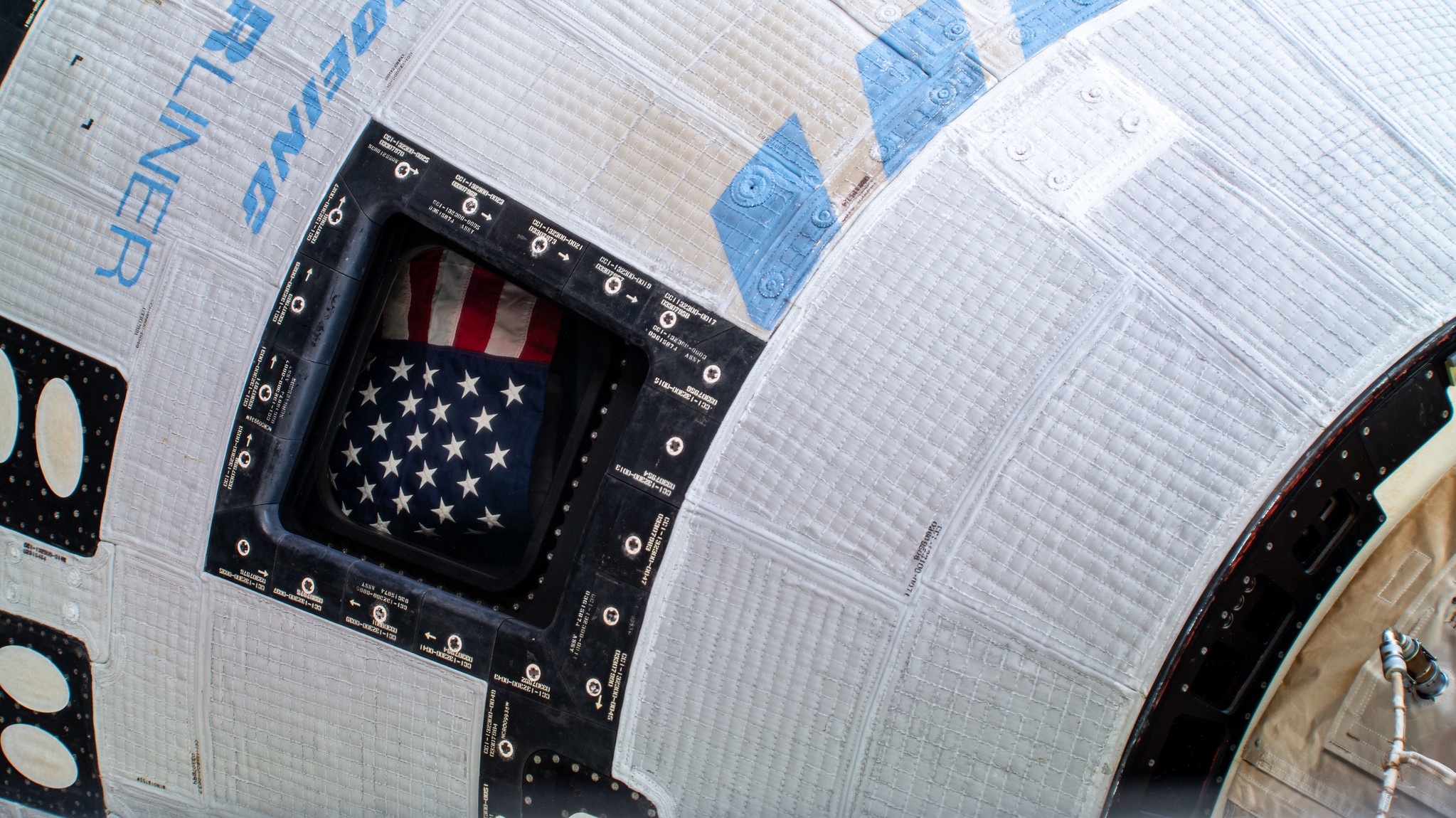
The American flag pictured inside the window of Boeing’s Starliner spacecraft at the International Space Station.
Credit: NASA
NASA’s live coverage of return and related activities will stream on NASA+, the NASA app, and the agency’s website. Learn how to stream NASA programming through a variety of platforms including social media.
NASA astronauts Butch Wilmore and Suni Williams launched aboard Boeing’s Starliner spacecraft on June 5 for its first crewed flight, arriving at the space station on June 6. As Starliner approached the orbiting laboratory, NASA and Boeing identified helium leaks and experienced issues with the spacecraft reaction control thrusters. For the safety of the astronauts, NASA announced on Aug. 24 that Starliner will return to Earth from the station without a crew. Wilmore and Williams will remain aboard the station and return home in February 2025 aboard the SpaceX Dragon spacecraft with two other crew members assigned to NASA’s SpaceX Crew-9 mission.
Preparations for Next Moonwalk Simulations Underway (and Underwater)
More than 100 scientists will participate in a field campaign involving a research vessel and two aircraft this month to verify the accuracy of data collected by NASA’s new PACE satellite: the Plankton, Aerosol, Cloud, ocean Ecosystem mission.
The process of data validation includes researchers comparing PACE data with data collected by similar, Earth-based instruments to ensure the measurements match up.
Since the mission’s Feb. 8, 2024 launch, scientists around the world have successfully completed several data validation campaigns; the September deployment — PACE-PAX — is its largest.
From sea to sky to orbit, a range of vantage points allow NASA Earth scientists to collect different types of data to better understand our changing planet. Collecting them together, at the same place and the same time, is an important step used to verify the accuracy of satellite data.
NASA’s Plankton, Aerosol, Cloud, ocean Ecosystem (PACE) satellite launched in February 2024 and is collecting observations of the ocean and measuring atmospheric particle and cloud properties. This data will help inform scientists and decision makers about the health of Earth’s ocean, land surfaces, and atmosphere and the interactions between them.
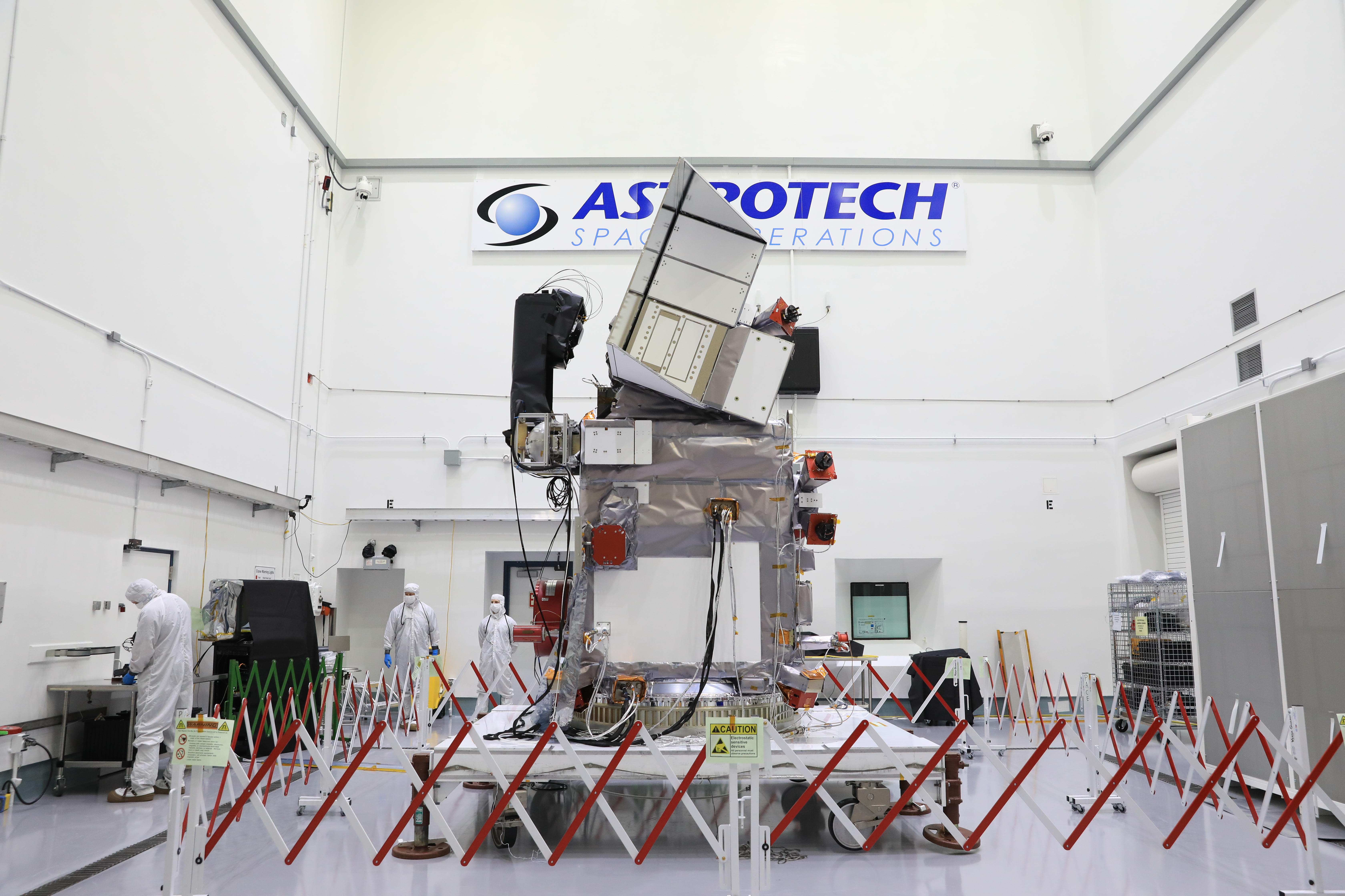
Technicians work to process the NASA’s Plankton, Aerosol, Cloud, ocean Ecosystem (PACE) observatory on a spacecraft dolly in a high bay at the Astrotech Space Operations Facility near the agency’s Kennedy Space Center in Florida on Monday, Dec. 4, 2023.
Credit: NASA/Kim Shiflett
To make sure the data from PACE’s instruments accurately represent the ocean and the atmosphere, scientists compare (or “validate”) the data collected from orbit with measurements they collect at or near Earth’s surface. The mission’s biggest validation campaign, called PACE Postlaunch Airborne eXperiment (PACE-PAX), began on Sept. 3, 2024, and will last the entire month.
“If we want to have confidence in the observations from PACE, we need to validate those observations,” said Kirk Knobelspiesse, mission scientist for PACE-PAX and an atmospheric scientist at NASA’s Goddard Space Flight Center in Greenbelt, Maryland. “This field campaign is focused on doing just that.”
Scientists will make measurements both from aircraft and ships. Based out of three locations across California — Marina, Santa Barbara, and NASA’s Armstrong Flight Research Center in Edwards — the campaign includes more than 100 people working in the field and several dozen instruments.
“This campaign allows us to validate data for both the atmosphere and the ocean, all in one campaign,” said Brian Cairns, deputy mission scientist for PACE-PAX and an atmospheric scientist at NASA’s Goddard Institute for Space Studies in New York City.
On the ocean, ships, including the National Oceanic and Atmospheric Administration (NOAA) research vessel Shearwater, will gather data on ocean biology and the optical properties of the water. Scientists onboard will gather water samples to help define the types of phytoplankton at different locations and their relative abundance, something that PACE’s hyperspectral Ocean Color Instrument measures from orbit.
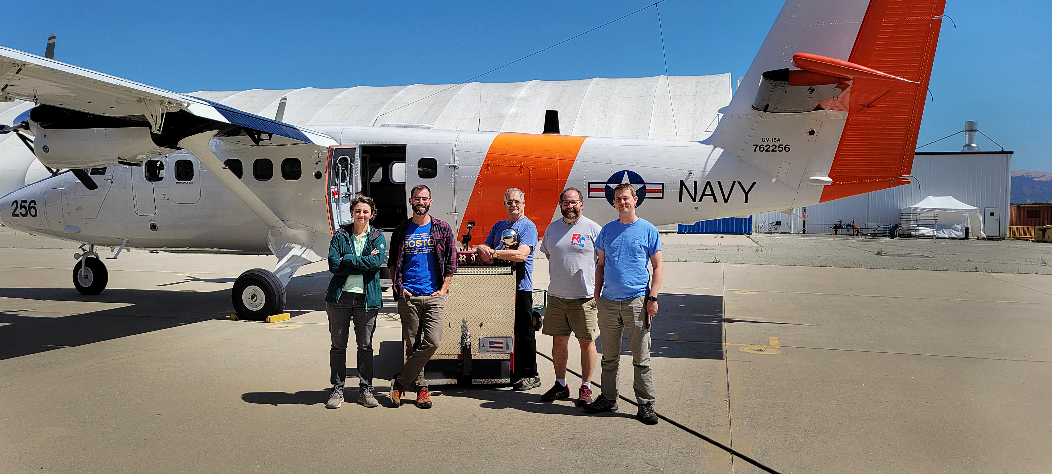
Members of the PACE-PAX team – from left to right, Cecile Carlson, Adam Ahern (NOAA), Dennis Hamaker (NPS), Luke Ziemba, and Michael Shook (NASA Langley Research Center) – in front of the Twin Otter aircraft as they prep for the start of the campaign.
Credit: Judy Alfter/NASA
Overhead, a Twin Otter research aircraft operated by the Naval Postgraduate School in Monterey, California, will collect data on the atmosphere. At altitudes of up to 10,000 feet, the aircraft will sample and measure cloud droplet sizes, aerosol sizes, and the amount of light that those particles scatter and absorb. These are the atmospheric properties that PACE observes with its two polarimeters, SPEXOne and HARP2.
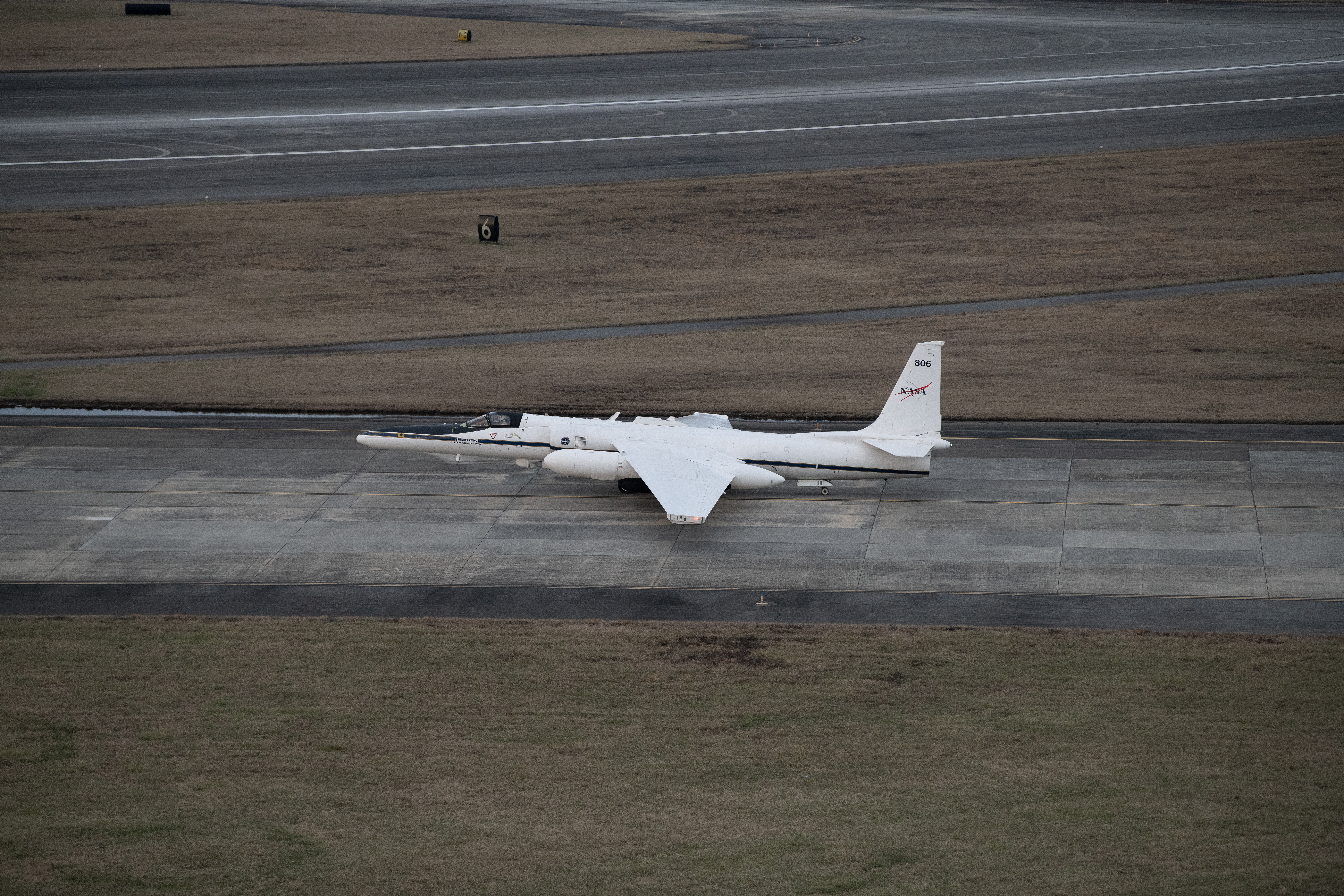
At a higher altitude — approximately 70,000 feet up — NASA’s ER-2 aircraft will provide a complementary view from above clouds, looking down on the atmosphere and ocean in finer detail than the satellite, but with a narrower view.
The NASA ER-2 high-altitude aircraft preparing for flight on Jan. 29, 2023. The aircraft is based at NASA’s Armstrong Flight Research Center Building 703 in Palmdale, California.
Credit: NASA/Carla Thomas
The plane will carry several instruments that are similar to those on PACE, including two prototypes of PACE’s polarimeters, called SPEXAirborne and AirHARP. In addition, two instruments called the Portable Remote Imaging SpectroMeter and Pushbroom Imager for Cloud and Aerosol Research and Development — from NASA’s Jet Propulsion Laboratory in Pasedena, California, and NASA’s Ames Research Center in California’s Silicon Valley, respectively — will measure essentially all the wavelengths of visible light (color). The remote sensing measurements are key for scientists who want to test the methods they use to analyze PACE satellite data.
Together, the instruments on the ER-2 approximate the data that PACE gathers and complement the in situ measurements from the ocean research vessel and the Twin Otter.
As the field campaign team gathers data, PACE will be observing the same areas of the ocean surface and atmosphere. Once the campaign is over, scientists will look at the data PACE returned and compare them to the measurements they took from the other three vantage points.
“Once you launch the satellite, there’s no more tinkering you can do,” said Ivona Cetinic, deputy mission scientist for PACE-PAX and an ocean scientist at NASA Goddard.
Though the scientists cannot alter the satellite anymore, the algorithms designed to interpret PACE data can be adjusted to make the measurements more accurate. Validation checks from campaigns like PACE-PAX help scientists ensure that PACE will be able to return accurate data about our oceans and atmosphere — critical to better understand our changing planet and its interconnected systems — for years to come.
“The ocean and atmosphere are such changing environments that it’s really important to validate what we see,” Cetinic said. “Understanding the accuracy of the view from the satellite is important, so we can use the data to answer important questions about climate change.”