Mirrors for the LDCM Operational Land Imager (OLI) Telescope.
NASA
Special Topics: LDCM and LDCM Components
The OLI telescope uses a four-mirror compact design. The optics are positioned inside a lightweight, yet highly stable, carbon composite optical bench (i.e., a substrate on which the optics are mounted) that has special features to control undesired stray light (stray light is any light entering the optics from someplace other than the observed Earth surface, or imaging “target”).
Because OLI is a push-broom instrument, as opposed to a scanner (or “whisk-broom”), it has a wide field-of-view to cover the entire ground swath width. Wide field-of-view telescopes are generally susceptible to stray light, so the OLI telescope is designed for improved stray light control. The number and shapes of the mirrors meet the required optical design parameters, like focal length, for example, within a size that also meets the volume and mass requirements for the instrument.
Note: The previous Landsat sensors have used scanner or “whisk-broom” technology. This means that a mirror scans from side-to-side across the satellite path directing light into the instrument detectors. The OLI uses push-broom technology meaning that an array of detectors is used to image the entire swath/width of the satellite path simultaneously.
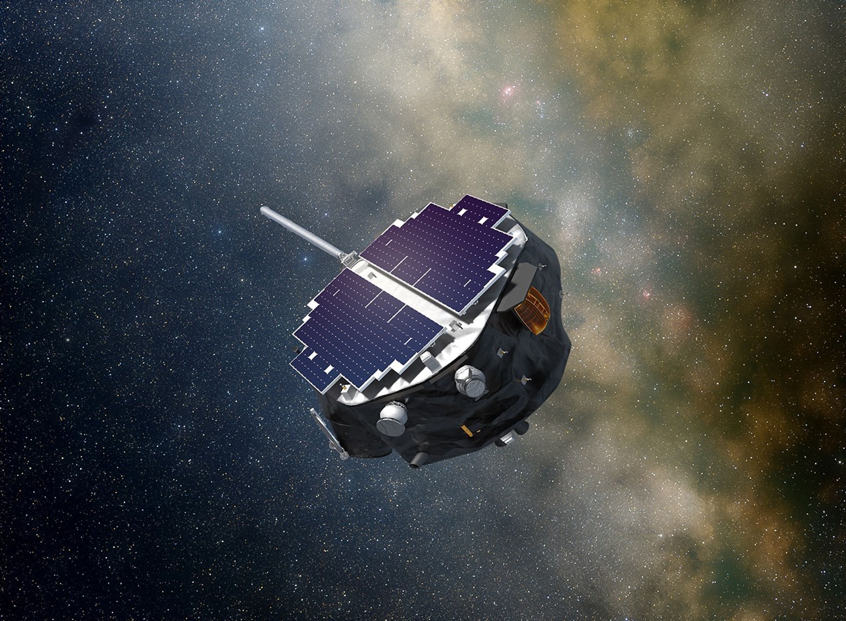
Landsat Data Continuity Mission Becomes an Observatory
TIRS being hoisted into place on the LDCM satellite in Gilbert, Ariz.
Orbital Science Corp
• Engineers at Orbital Sciences Corporation, Gilbert, Ariz., have installed the Thermal Infrared Sensor (TIRS) instrument back onto to the Landsat Data Continuity Mission (LDCM) spacecraft. With both the Operational Land Imager (OLI) and TIRS instruments now on the spacecraft, LDCM is a complete observatory.After the TIRS instrument was shipped to Orbital in February, engineers discovered that helium had leaked from the TIRS cryogenic cooler. The cooler keeps the detectors extremely cold, which is required for the instrument to detect thermal infrared radiation emitted from Earth. The leak was quickly repaired, the cooler was re-pressurized with helium, and TIRS was re-installed onto the instrument deck of the spacecraft. Once the TIRS instrument is electrically connected later this month, TIRS will be ready to begin environmental testing with the rest of the observatory.
The engineering team at NASA’s Goddard Space Flight Center in Greenbelt, Md., built TIRS on an accelerated schedule, going from a design on paper to a completed instrument in 43 months. An instrument of this type usually takes another year to complete.
Under contract to NASA, Orbital is responsible for providing the spacecraft bus, installing the science instruments and performing system-level integration and testing of the Observatory prior to launch. Ball Aerospace & Technologies Corp. built the OLI. The USGS developed the LDCM ground system.
A NASA-sponsored team at the University of Iowa (UI) is restoring and advancing the nation’s capability to make high-fidelity magnetic field measurements needed to investigate space weather that can impact our communication and power grids on Earth and our assets in space.
Fluxgate magnetometers are widely-used space science and space weather instruments, but they depend on a legacy component—a ferromagnetic core—that was developed and manufactured for the U.S. Navy using technology that has been subsequently lost to the civilian community.
The UI team manufactures new fluxgate cores using a method that does not rely on legacy processes or materials and then integrates these cores into modern spaceflight magnetometers. The ferromagnetic cores are produced starting from base metal powders that are melted into custom alloys, rolled into thin foils, formed into the desired geometry of the fluxgate core, and artificially aged using heat to optimize their magnetic properties. The resulting cores are integrated into a complete fluxgate sensor ready for spaceflight applications.
Designing, prototyping, and manufacturing the cores, sensors, and paired electronics in house allows the team to explore new sensor geometries that are compatible with different missions. Most recently, the UI team developed a new core to be used in the Space Weather Iowa Magnetometer (SWIM). While the SWIM core is based on a core previously developed for the MAGnetometers for Innovation and Capability (MAGIC) Tesseract sensor that recently launched on NASA’s TRACERS (Tandem Reconnection and Cusp Electrodynamics Reconnaissance Satellites) mission the SWIM core is miniaturized and retains the same level of performance. The first flight opportunity for the SWIM fluxgate is on the University of Oslo’s ICI-5bis sounding rocket mission that is scheduled to launch in winter 2025/2026 from the Andoya Space Sub-Orbital range in Norway.
Integration of the SWIM sensor for the ICI-5bis Suborbital Sounding Rocket.
Fluxgate magnetometers sense the magnetic field by detecting the electromagnetic force (EMF) induced by the changing magnetic flux. Current is driven into the drive winding (the interior winding on the fluxgate core) creating a magnetic field. When the ferromagnetic material in the cores experiences the magnetic field, its relative permeability (the intrinsic magnetic property of the metal within the core) changes. As the relative permeability changes, a voltage is induced in the sense winding (the outer winding on the core). By knowing the amount of current driven into the core and the voltage that was induced in the sense winding, we can understand the magnetic field that the sensor is experiencing. Most in-space magnetometers are not located onboard the main body of the spacecraft; instead, they are placed on booms to ensure that the magnetic fields produced by the electronics and magnetic materials onboard the spacecraft do not interfere with the sensor.
Example noise plot of a SWIM fluxgate core showing <5pT/√Hz at 1 Hz noise performance.
The manufacturing process for these new cores is now well documented and ~90% of the cores produced have a noise floor that is comparable or better than previous legacy cores. Consequently, UI can reliably mass-produce cores for the SWIM payload and potential future follow-on missions.
The Tesseract sensor from the MAGIC payload on the TRACERS mission (Left). The SWIM sensor (Right) is more compact, simpler to assemble, and provides equal or better performance in the relevant figures of merit (mass, power, volume, magnetic noise, offset, etc.)
Credit: NASA GSFC
The new SWIM magnetometer design reflects three significant changes compared to the previous MAGIC instrument. The sensor has been simplified and shrunk. Its power consumption has been reduced without sacrificing measurement performance. Both these changes aid its accommodation on a magnetometer boom. In addition, the topology of the paired electronics in each magnetometer channel has been redesigned, which allows use of lower-performance parts that tolerate a higher radiation exposure.
Reduced Sensor size: The compact SWIM design reduces the sensor size by ~30% compared to the MAGIC sensor, with further reduction to the sensor mass likely as the mechanical design is optimized. The MAGIC Tesseract design used six cores whereas the SWIM sensor utilizes three smaller cores of the same geometry. Mass is a major performance driver for deployable boom design and vehicle dynamics. The SWIM sensor can also be manufactured with a lightweight carbon-composite cover (or the cover can be omitted) to achieve a sensor mass of ~110 g, which would enable the sensor to be easily accommodated on small satellite booms.
SWIM sensor magnetic calibration at the Goddard Space Flight Center.
Reduced Power consumption: Using three smaller cores with improved metallurgy instead of six large racetrack cores reduced the power consumption of the SWIM sensor by a factor of two compared to the MAGIC sensor. Although this power reduction is modest compared to the total consumption of the instrument, it positively impacts the capability for boom deployment. Significant reduction in heat dissipation at the sensor minimizes the spot-heating of the deployable boom and reduces thermal gradients that can drive boom deformation/rotation, which impacts the pointing knowledge at the sensor. These improvements to the sensor have been achieved without impacting the measurement fidelity. In fact, prototype miniaturized SWIM race-track cores are outperforming the previous MAGIC cores due to their improved metallurgy.
Updated Electronics Topology: The MAGIC electronics use a traditional analog demodulator fluxgate and magnetic feedback design. This design requires high-performance components to be able to resolve small variations in large ambient magnetic fields. There are radiation limitations to these high-performance components making it difficult for the MAGIC design to operate in a high-radiation environment. To mitigate these issues, the SWIM design employs digital demodulation instead of analog demodulation and provides magnetic feedback via temperature-compensated, digital, pulse-width-modulation. This update to the electronics enables SWIM to potentially be used in long-duration and/or high-reliability operational applications such as radiation belt missions or planetary missions with long cruise phases.
The SWIM fluxgate design allows for more future applications in a variety of environments without sacrificing the performance seen on the MAGIC sensors. The UI team is looking forward to multiple upcoming flight opportunities for SWIM, including on the Observing Cusp High-altitude Reconnection and Electrodynamics (OCHRE) and ICI5bis sounding rockets.
Project Lead(s): Dr. David Miles, University of Iowa